Intelligent Plant System (IPS)
The Intelligent Plant System (IPS) project is a collaboration between the Mora Lab from the department of geography at the University of Hawaii, and the RIP Lab, whose goal is to design and develop a machine that can monitor plant growth in response to climate change. Currently, very limited experimental data is available regarding plant response to changing climate, as it is a difficult engineering problem to create a controlled environment to incubate plant growth over a given subset of independent environmental perturbations. The goal of this design initiative is to create a cost-conscious machine capable of monitoring and controlling carbon dioxide (CO2), ozone (O3), temperature, and humidity levels in an artificial environment. This machine should be scalable to allow for a large number of test subjects to achieve scientific validity of results for all of the control variables mentioned above.Project Abstract
Hardware and Prototypes


Carbon Dioxide Control Demo
The carbon dioxide control chamber consists of six primary parts: (1) an air compressor for pumping in atmospheric air into the system, (2) a filter for removing O3 and CO2 from the incoming atmospheric air, (3) a CO2 tank to provide a stream of pure CO2 into the system, (4) a variable flow restrictor (valve), controlled by a stepper motor, (5) associated control electronics, and (6) the plant chamber. The incoming compressed air is first filtered to a point such that the CO2 concentration is somewhere below the desired setpoint temperature. The filtered air is then mixed with a stream of pure CO2 fed by the CO2 tank, the flow rate of which, is controlled by the variable restrictor. By controlling the stepper motor attached to the variable restrictor, we can control the CO2 concentration of the air flowing into the plant chamber. A demo video of the carbon dioxide control chamber is shown below.
Music: Carefree Kevin MacLeod (incompetech.com)
Temperature Control Demo
The temperature control chamber consists of six primary parts: (1) an resistance heater for heating the plant chamber, (2) a forced convection heat exchanger for cooling the chamber, (3) a cold water/coolant source, (4) a PWM controllable pump, (5) associated control electronics, and (6) the plant chamber. Currently, the temperature in the chamber is maintained by controlling the coolant flow speed into the heat exchanger–the resistance heater remains on at a constant heat output. In future iterations of this system, we will be able to better control the temperature by intelligently controlling the voltage into the resistor heater, the resistor heater fan speed, the heat exchanger flow rate, and the heat exchanger fan speed. A demo video of the carbon dioxide control chamber is shown below.
Music: Life of Riley Kevin MacLeod (incompetech.com)
Plant Manipulator and Water Delivery Demo
The plant manipulator utilizes a three-axis gantry system to manipulate the position of a row of plants in a given space as desired. This design is scalable to allow for the manipulation of many more plants per duty cycle. The current soil moisture of each plant is independently measured for each plant by measuring the change in mass of each plant “pot” over time via a strain gauge. The water delivery to the plants is gravity fed, using a solenoid to precisely control water flow.
Carbon Dioxide Control System


The second prototype consists of a closed-loop system that has the following materials:
- Styrofoam Chamber
- 1 Tetra Whisper Air Fish Tank Pump
- 1 CO2 Sensor
- 1 Three Way Solenoid
- 1 Two Way Solenoid
- 1 Arduino
- 3 Computer Fans
- 2 Relays
- 1 Soda-Lime Cartridge/Soda-Lime Material
Code
There are three different subprograms that create the Arduino code in order to control the concentration of the chamber. The first being if the actual concentration is higher than the desired. Second, if the actual concentration is lower than the desired. Lastly, if the actual concentration is within the range of the desired. Depending on the readings from the CO2 sensor, each of these programs manipulate the switches of the solenoids to control the flow of the air.
How it Works:
The CO2 control code reads the concentration of CO2 in the line and then adjusts it to the target CO2 by either adding CO2 or running it through soda-lime, to increase or reduce the concentration, respectively. Since CO2 addition is much faster and much less stable than reducing, a basic Fuzzy Logic algorithm had to be introduced that analyzes the difference between the read CO2 concentration and the target amount. It then adds a calibrated amount of pure CO2 (calculated from experiments) and reads the concentration for five minutes to give ample time for the CO2 to mix with the existing air in the chamber. This process loops until the desired concentration is met. If one needed to reduce the concentration of the air in the chamber, Fuzzy Logic is not needed as we found that running the air through the soda-lime cartridge until the CO2 sensor reads the target concentration, works fine.

Current Studies
With this current system, there is only one CO2 sensor that measures the current concentration in the chamber. The goal is to include three more sensors in various locations of the chamber to collect data from the entire chamber rather than the air that is being pulled. An average will then be calculated to increase the accuracy of the reading for the Arduino.
One Tetra Whisper Air pump for 300 gallon fish tanks is being utilized to provide the necessary flow throughout this system. We did not consider the friction throughout the tubing and solenoids, because in an academic setting, we usually ignore that factor. Although after various testing, we have to consider friction because as the air that flows towards the soda-lime cartridge, has a flow rate that is significantly reduced compared to the output of the pump. After a few experiments, it took six times as long to decrease 100 ppm than increasing it by 100 ppm. Realizing this problem, we are currently researching an in-line air pump that will be placed right in front of the cartridge so that it can provide the necessary flow rate to push air faster throughout the soda-lime.
Next Generation Carriage to that Records Mass and Maintains Soil Moisture
The watering portion of the Intelligent Planting System is a gantry style machine with load cells that record the change in the mass of specimens and deposits water when mass decreases past a threshold due to evaporation. The design features a carriage that runs on common industrial steel shelving with the capacity to maintain up to 90 potted plants with a pot diameter of 4” and a mass of up to 5kg each. Situated on the carriage are 6 aluminum load cells that measure the mass of each potted plant using a variable resistance strain gauge adhered to two opposing faces of the load cell. The carriage runs beneath the potted plants which sit on angled steel beams and are lifted up off of the steel beams when measured. A Sarrus linkage driven by a threaded rod actuates the lift. Timing belts drive the carriage movement from row to row. Water is deposited just above the lip of each pot with via gravity fed reservoir and exits a micropipette tip. Deposition is based purely on a time delay via solenoid valve and results in a fine deposition of approximately 0.5g of water at a time. All of the components used in latest iteration of the Intelligent Planting system are affordably and commercially readily available with the exception of the custom printed circuit board and Sarrus linkage.
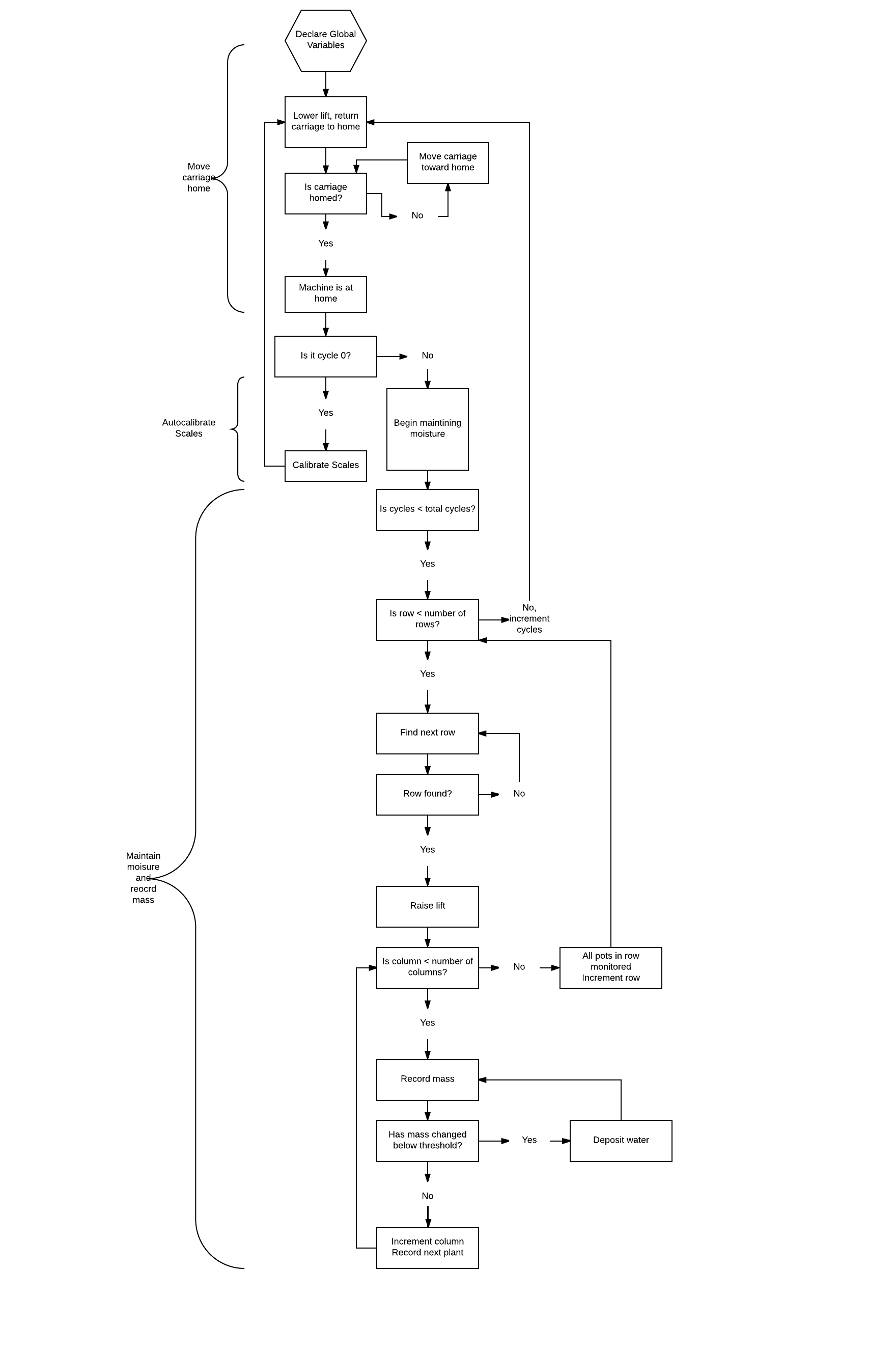
The image above is an extremely simplified logic diagram for the various operations that the carriage must perform.

The image above displays the Sarrus linkage portion of the carriage along with the watering system and load cells visible.
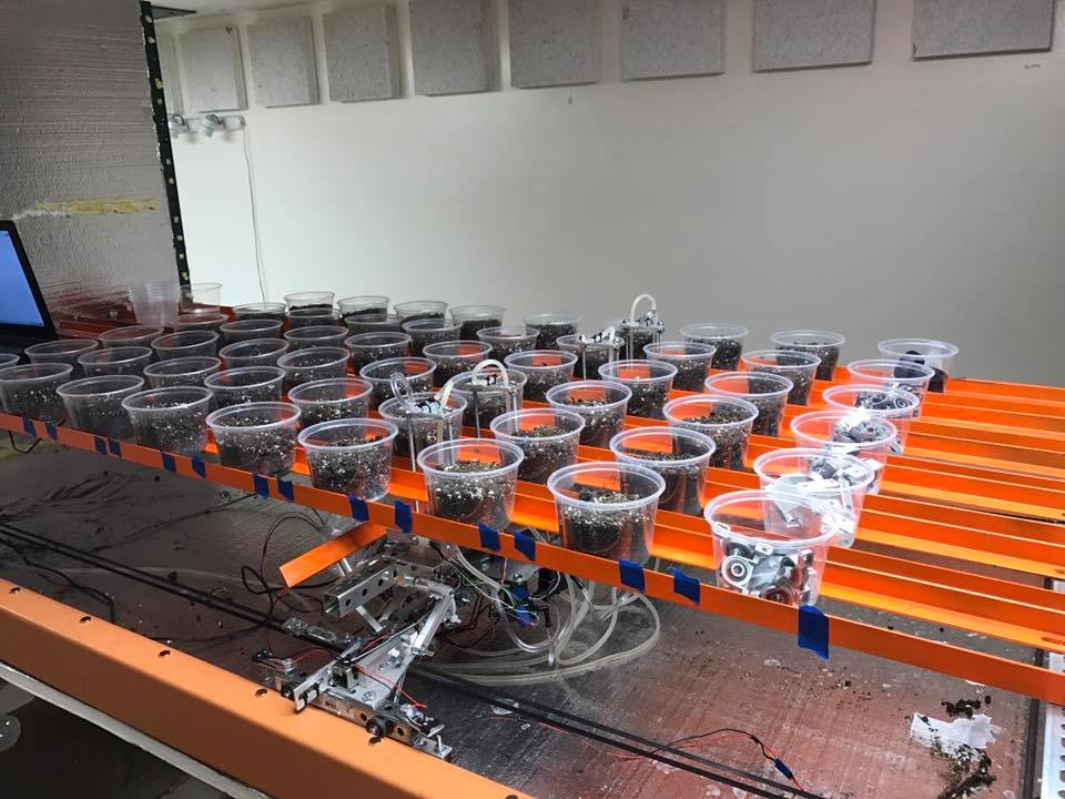
The image above displays the carriage running beneath pots, recording the masses and maintaining the numerous treatments of varying soil moisture.
Machine Performance

Above: The evaporation rate of a potted plant with 36g (+/- 1g) of water in 700g (+/- 1g) sand media. The change in mass over a 20 hr period in a climate controlled room was 4.1g or 11.4% of the initial water mass. The accuracy difference between measured and actual mass is likely due to an error in a calibration constant.

Above: 100g (+/-1g) of potting soil was placed into a pot with 59 (+/- 1g) grams of water added. The mass of water was maintained over a duration of 27 hours. One standard deviation was 0.288g. The machine took approximately 3 hours to set up and had a cycle time of 0.67 hours or 40.2 minutes, a bit slower than stated in the table below due to a different lift drive design.
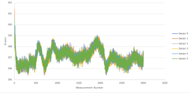
Above: 3002 recorded measurements of 400g (+/- 1g) masses. Measurements were recorded over the course of approximately 3 days.